Surface Roughness
All mechanical parts must be manufactured through various machining processes. However, due to the limitations of machining equipment, cutting tools, working environments, and operator skill levels, the actual geometric parameters of the machined parts often cannot fully match the ideal conditions specified in the drawings. The difference between the actual state and the ideal state is collectively referred to as machining error.According to different geometric parameters, machining errors can be divided into dimensional errors, geometric shape errors, and surface roughness. This article will focus on surface roughness, a key indicator of machining quality.
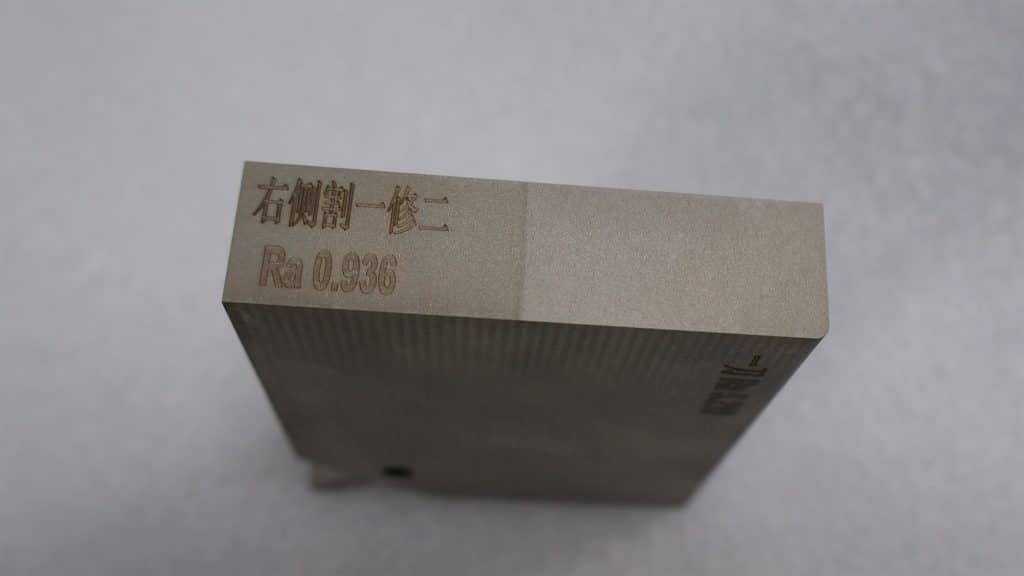
The illustration shows the use of a “cut one, regrind twice” process on a hard material (such as SKD11 in its heat-treated condition), achieving a surface roughness of approximately Ra 0.9 μm.
Definition and Classification of Surface Roughness
Surface roughness refers to the small peaks and valleys on a part’s surface formed during machining, representing a type of microscopic geometric deviation. Typically, surface features with wavelengths less than 1 mm are classified as surface roughness, those between 1 mm and 10 mm as surface waviness, and features greater than 10 mm as macro-geometric surface form. The magnitude of surface roughness directly reflects the smoothness of a part’s surface—the smaller the value, the smoother the surface.
Causes of Surface Roughness Formation
So, how is surface roughness formed? It mainly arises from the friction between the cutting tool and the workpiece surface during machining, the plastic deformation generated during chip separation, and high-frequency vibrations within the process system. Different machining methods and materials leave textures on the surface that vary in depth, density, and pattern.
Effects of Surface Roughness on Part Performance
Surface roughness has a significant impact on the functional performance of a part, mainly in the following aspects: friction and wear, fatigue strength, corrosion resistance, and the fit between mating parts. An appropriate surface roughness can not only extend the service life of a part but also optimize its operational stability.
Difference Between Surface Roughness and Surface Finish
In practical applications, surface roughness and surface finish are often confused, but they are fundamentally different. Surface roughness is a quantitative, measurable microscopic geometric parameter, usually expressed in values such as Ra or Rz. In contrast, surface finish is a more subjective, qualitative description based on visual appearance and tactile feel. Although the two can be correlated using reference charts, roughness has a precise measurement formula, whereas surface finish often relies on comparison with standard reference samples.
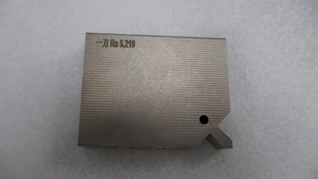
The illustration shows the use of a “single-pass cutting” process on a hard material (such as SKD11 in its heat-treated condition), achieving a surface roughness of approximately Ra 5.2 μm.
Surface Roughness Achievable by Common Machining Methods
The surface roughness achievable varies significantly depending on the machining method. Common processes such as turning, milling, grinding, wire EDM, and electrical discharge machining each have their applicable range and precision level. Specifically:
Turning is a cutting process in which the workpiece rotates while the cutting tool moves linearly or along a curve on a plane. It is commonly used for machining external and internal cylindrical surfaces, end faces, tapered surfaces, contoured surfaces, and threads. The machining accuracy and surface roughness can be generally classified as follows:
- Rough machining: IT11, Ra 20–10 μm
- Semi-finishing: IT10–9, Ra 10–2.5 μm
- Finishing: IT8–IT7, Ra 1.6–0.8 μm
- Mirror turning: IT7–IT5, Ra 0.04–0.01 μm
Milling uses multi-edged rotating cutters for material removal, offering high efficiency. It is suitable for machining planes, grooves, complex surfaces, and mold surfaces. The typical accuracy ranges are:
- Rough machining: IT11–IT13, Ra 20–5 μm
- Semi-finish machining: IT8–IT11, Ra 10–2.5 μm
- Finish machining: IT8–IT7, Ra 5–1.6 μm
Grinding is a finishing process that removes material using abrasives and grinding tools. It is widely used in applications requiring high precision. The surface roughness can be classified as follows:
- General grinding: Ra 1.25–0.16 μm
- Precision grinding: Ra 0.16–0.04 μm
- Ultra-precision grinding: Ra 0.04–0.006 μm
In wire cutting (taking medium-speed wire cutting as an example), the surface roughness improves with the number of cutting passes:
- First cut: Ra ≥ 2.5 μm
- Second cut: Ra ≈ 1.6 μm
- Third cut and beyond: Ra can reach 0.8 μm
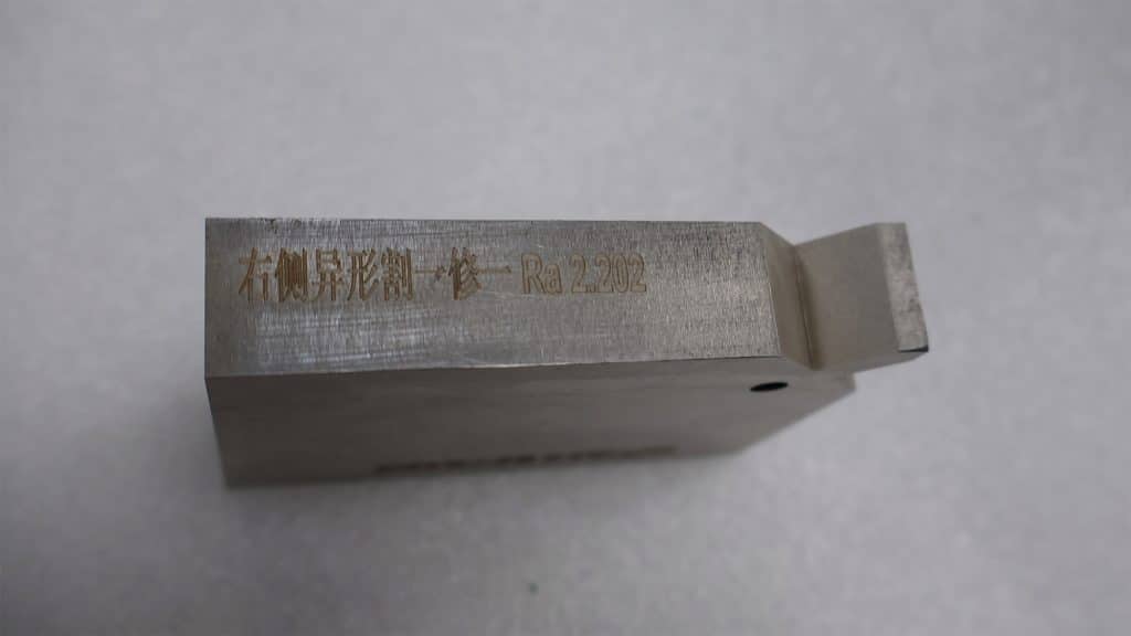
As shown in the figure, using the “cut-and-spot-finish” process on hard materials (such as SKD11 in the heat-treated condition) results in a surface roughness of approximately Ra 2.2 μm.
EDM removes material through electrical erosion and is suitable for parts with high hardness or complex shapes. The typical surface roughness is as follows:
- Rough machining: Ra 6.3–12.5 μm
- Semi-finish machining: Ra 1.6–3.2 μm
- Finish machining: Ra 0.4–0.8 μm
From a comprehensive surface finish perspective, the typical ranking of common machining methods is: grinding > EDM > medium-speed wire cutting > precision milling > general milling.
Therefore, in the typical machining process for high-precision parts, rough and semi-finish machining is usually first carried out by milling, followed by heat treatment to increase material hardness. Next, wire cutting is applied to complex shapes or holes. Finally, key mating surfaces are ground to ensure dimensional accuracy and surface quality.
In short, milling shapes the part, wire cutting handles “hard material profiling,” and grinding provides the final “polish and finishing touch.”
Indication of Surface Roughness and Interpretation of Common Grades
In international notation, different regions use different methods. For example, in Japan, surface finish is commonly indicated by the letter “G” or an inverted triangle symbol.

The letter G indicates that grinding is required at the specified location.For example:
▽ corresponds to Ra = 12.5–50 μm
▽▽▽▽ corresponds to Ra < 0.2 μm
▽▽▽ corresponds to Ra = 0.2–0.8 μm
▽▽ corresponds to Ra = 1.6–6.3 μm

So what does the common Ra 1.6 μm actually represent?
It corresponds to a medium-to-high surface quality. Machining marks are hardly visible to the naked eye. This level of roughness is suitable for fixed support surfaces, bushings, bearing seats, and press-fit holes for locating pins that require alignment or fit.
Examples include the tooth surfaces of grade-8 gears, gear rack teeth, threaded contact surfaces in transmissions, and journal surfaces for low-speed shafts.
In the aerospace field, some non-mating critical parts also commonly adopt this roughness level.
Methods for Measuring Surface Roughness
To accurately assess surface roughness, commonly used measurement methods include the comparative method and the stylus (contact) method.
Comparative Method
Suitable for on-site workshop use, this method allows for quick assessment by comparing the surface with a reference standard. It is commonly used for medium or relatively rough surfaces.
Stylus (Contact) Method
The stylus (contact) method for measuring surface roughness uses a diamond stylus with a tip radius of approximately 2 μm, which moves slowly along the surface being measured. The vertical displacement of the stylus is converted into an electrical signal by an electronic displacement sensor. This signal is then amplified, filtered, and processed, and the roughness value is either displayed directly on an instrument or recorded to generate a profile curve.Depending on their functionality, such instruments can be classified into two types:Surface roughness testers, which only display roughness values.Surface profilometers, which can both display roughness values and record surface profiles.Both types are equipped with built-in electronic circuits or computer systems capable of automatically calculating various evaluation parameters, including the arithmetic mean deviation (Ra), ten-point height of micro-unevenness (Rz), and maximum profile height (Ry). These instruments are highly efficient and are suitable for measuring surface roughness in the Ra range of 0.025–6.3 μm.
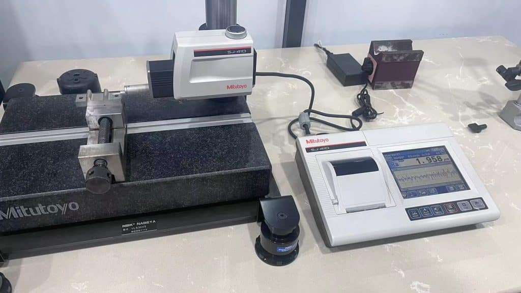
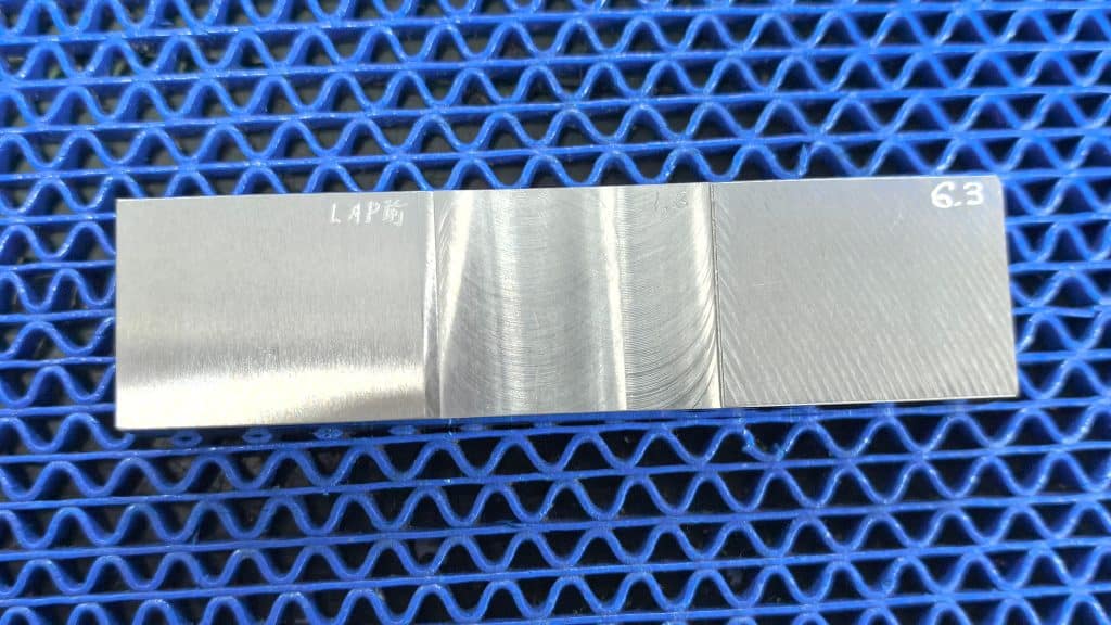
This figure illustrates the measurement of surface roughness on a heat-treated SKD11 workpiece using the stylus (contact) method. The workpiece was processed by wire cutting with the “cut-and-spot-finish” method (parameters: 1 cut + 1 finish). The arithmetic average roughness (Ra) measured by a Mitutoyo surface roughness tester was 1.958 μm.
By optimizing machining processes and controlling surface roughness, we can enhance part performance while extending service life—a goal that modern precision manufacturing continuously strives to achieve.